Low power factor is expensive and inefficient. Many utility companies charge you an additional fee if your power factor is less than 0.95. Low power factor also reduces your electrical system’s distribu- tion capacity by increasing current flow and causing voltage drops. This fact sheet describes power factor and explains how you can improve your power factor to reduce electric bills and enhance your electrical system’s capacity.
What is Power Factor?
Reducing Power Factor Cost
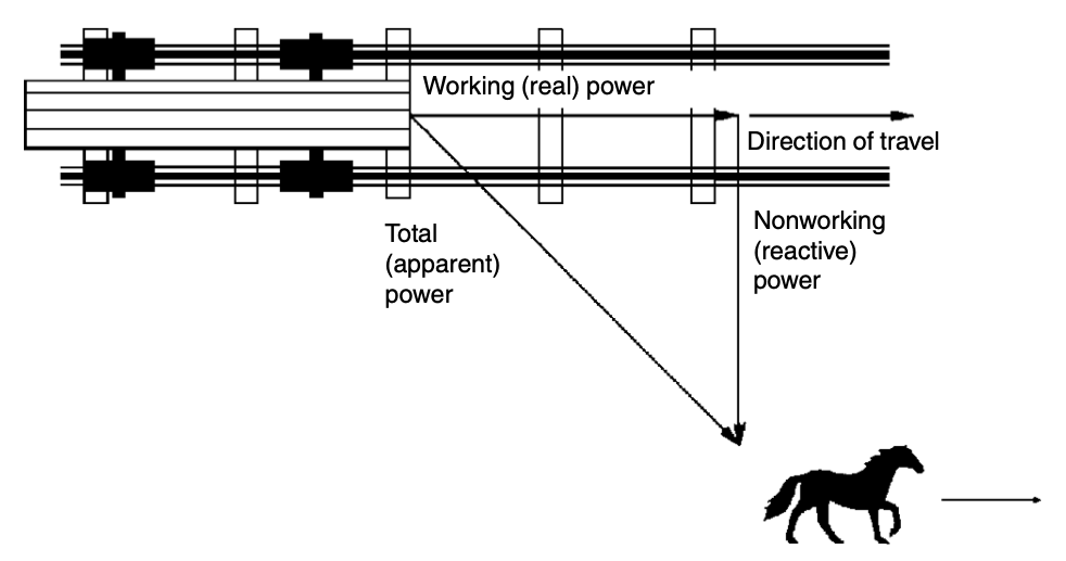
To understand power factor, visualize a horse pulling a railroad car down a railroad track. Because the railroad ties are uneven, the horse must pull the car from the side of the track. The horse is pulling the railroad car at an angle to the direction of the car’s travel. The power required to move the car down the track is the working (real) power. The effort of the horse is the total (apparent) power. Because of the angle of the horse’s pull, not all of the horse’s effort is used to move the car down the track. The car will not move sideways; therefore, the sideways pull of the horse is wasted effort or nonworking (reactive) power.
The angle of the horse’s pull is related to power factor, which is defined as the ratio of real (working) power to apparent (total) power. If the horse is led closer to the center of the track, the angle of side pull decreases and the real power approaches the value of the apparent power. Therefore, the ratio of real power to apparent power (the power factor) approaches 1. As the power factor approaches 1, the reactive (nonworking) power approaches 0.
Power Factor = Real Power /Apparent Power
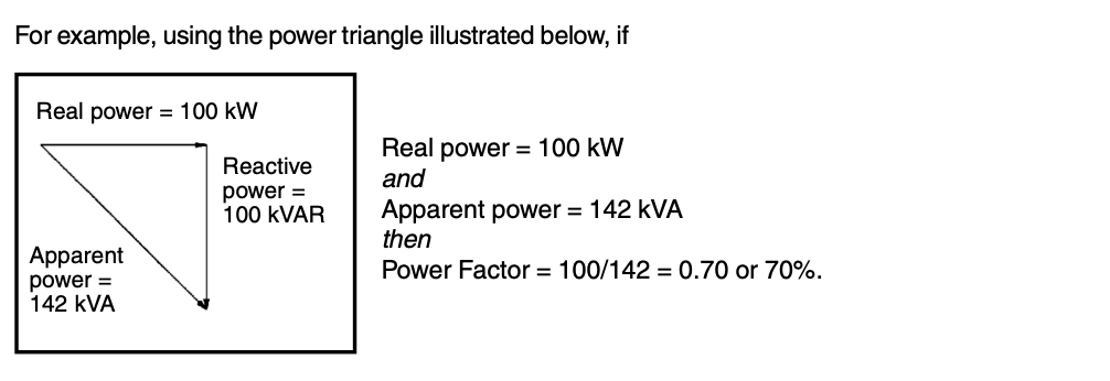
This indicates that only 70% of the current provided by the electrical utility is being used to produce useful work.
Cause of Low Power Factor
Low power factor is caused by inductive loads (such as transformers, electric motors, and high-intensity discharge lighting), which are a major portion of the power consumed in industrial complexes. Unlike resistive loads that create heat by consuming kilowatts, inductive loads require the current to create a magnetic field, and the mag- netic field produces the desired work. The total or apparent power required by an inductive device is a composite of the following:
• Real power (measured in kilowatts, kW)
• Reactive power, the nonworking power caused by the magnetizing current, required to operate the device (measured in kilovars, kVAR)
Reactive power required by inductive loads increases the amount of apparent power (measured in kilovolt amps, kVA) in your distribution system. The increase in reactive and apparent power causes the power factor to decrease.
Why Improve Your Power Factor?
Some of the benefits of improving your power factor are as follows:
- Your utility bill will be smaller. Low power factor requires an increase in the electric utility’s generation and transmission capacity to handle the reactive power component caused by inductive loads. Utilities usually charge a penalty fee to customers with power factors less than 0.95. You can avoid this additional fee by increasing your power factor.
- Yourelectricalsystem’sbranchcapacitywillincrease.Uncorrectedpowerfactorwillcausepowerlossesinyour distribution system. You may experience voltage drops as power losses increase. Excessive voltage drops can cause overheating and premature failure of motors and other inductive equipment.
Correcting Your Power Factor
Some strategies for correcting your power factor are:
- Minimize operation of idling or lightly loaded motors.
- Avoid operation of equipment above its rated voltage.
- Replace standard motors as they burn out with energy-efficient motors. Even with energy-efficient motors, however, the power factor is significantly affected by variations in load. A motor must be operated near its rated ca- pacity to realize the benefits of a high power factor design.
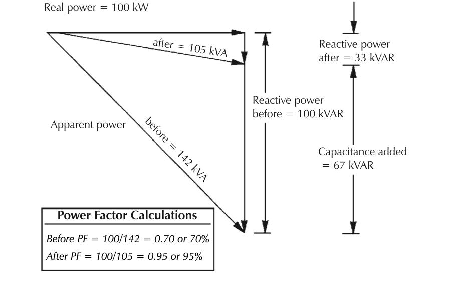
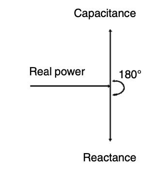
- Install capacitors in your AC circuit to decrease the magnitude of reactive power. As shown in the diagram at right, reactive power (measured in kVARs) caused by inductance always acts at a 90° angle to real power. Capacitors store kVARs and release energy opposing the reactive energy caused by the inductor. This implies that inductance and capacitance react 180° to each other. The presence of both in the same circuit results in the continuous alternating transfer of energy between the capacitor and the induc- tor, thereby reducing the current flow from the generator to the circuit. When the circuit is balanced, all the energy released by the inductor is absorbed by the capacitor. In the diagram below, the power triangle shows an initial 0.70 power factor for a 100-kW (real power) inductive load. The reactive power required by the load is 100 kW. By installing a 67-kW capacitor, the apparent power is reduced from 142 to 105 kVA, resulting in a 26% reduction in current. Power factor is improved to 0.95. In the “horse and railcar” analogy, this is equivalent to decreasing the angle the horse is pulling on the railcar by leading the horse closer to the center of the railroad track. Because the side pull is minimized, less total effort is required from the horse to do the same amount of work. Capacitor suppliers and engineering firms can provide the assistance you may need to determine the optimum power correction factor and to correctly locate and install capacitors in your electrical distribution system.